
Renga Structural
Renga – Renga is a BIM system for the architectural, structural design and MEP engineering of buildings.
The products of Renga Software are intended for integrated design: the information model of a construction object created in the Renga system can be used in other stages of its life cycle.
Automated Reinforcement
To provide development of reinforced concrete structures in 3D, highly efficient reinforcing tools are implemented in Renga. The Automated Reinforcement tool significantly speeds up rebar distribution in cast reinforced concrete elements and generates reinforced concrete drawings without much effort. Apart from the reinforcement of objects, the Renga Automatic Reinforcement tool has features for automatic steel reinforcement of holes and openings in floors and walls. Plus the reinforcement analysis is linked to any holes or openings and adjusts itself following changes made to the building’s structural design.
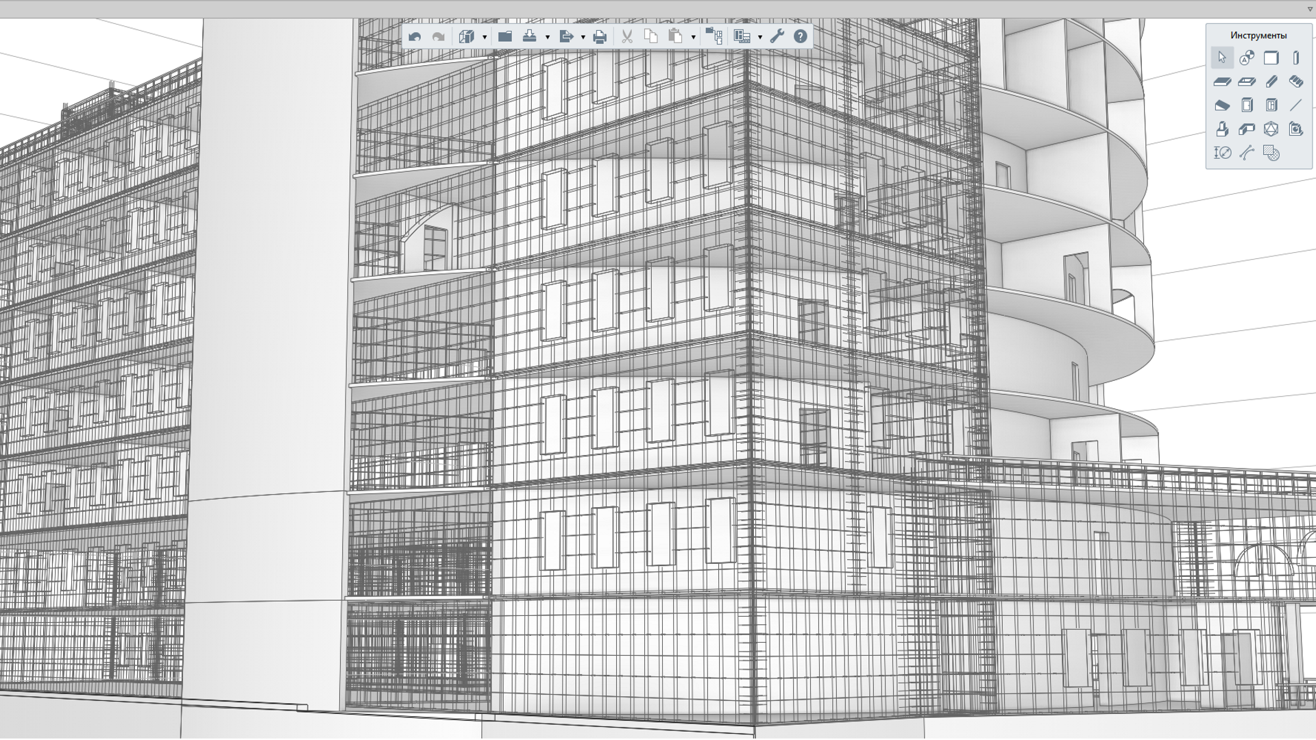
Figure 1: Automated Reinforcement
Steel Structures Design
Using Renga software features, a user can design steel structures and facilities of any level of complexity. The assembly tool allows users to create trusses suitable for shipment, columns, etc. and apply them during building or facility structural scheme design. Easy-to-use 3D snaps and the 3D measure mode will noticeably enhance the accuracy and speed up the process of accurately placing structural elements. Profile editor will save you the trouble of looking for structural elements with non-standard profiles on the Internet. You can create a steel structure profile of any form within minutes and use them in your projects.
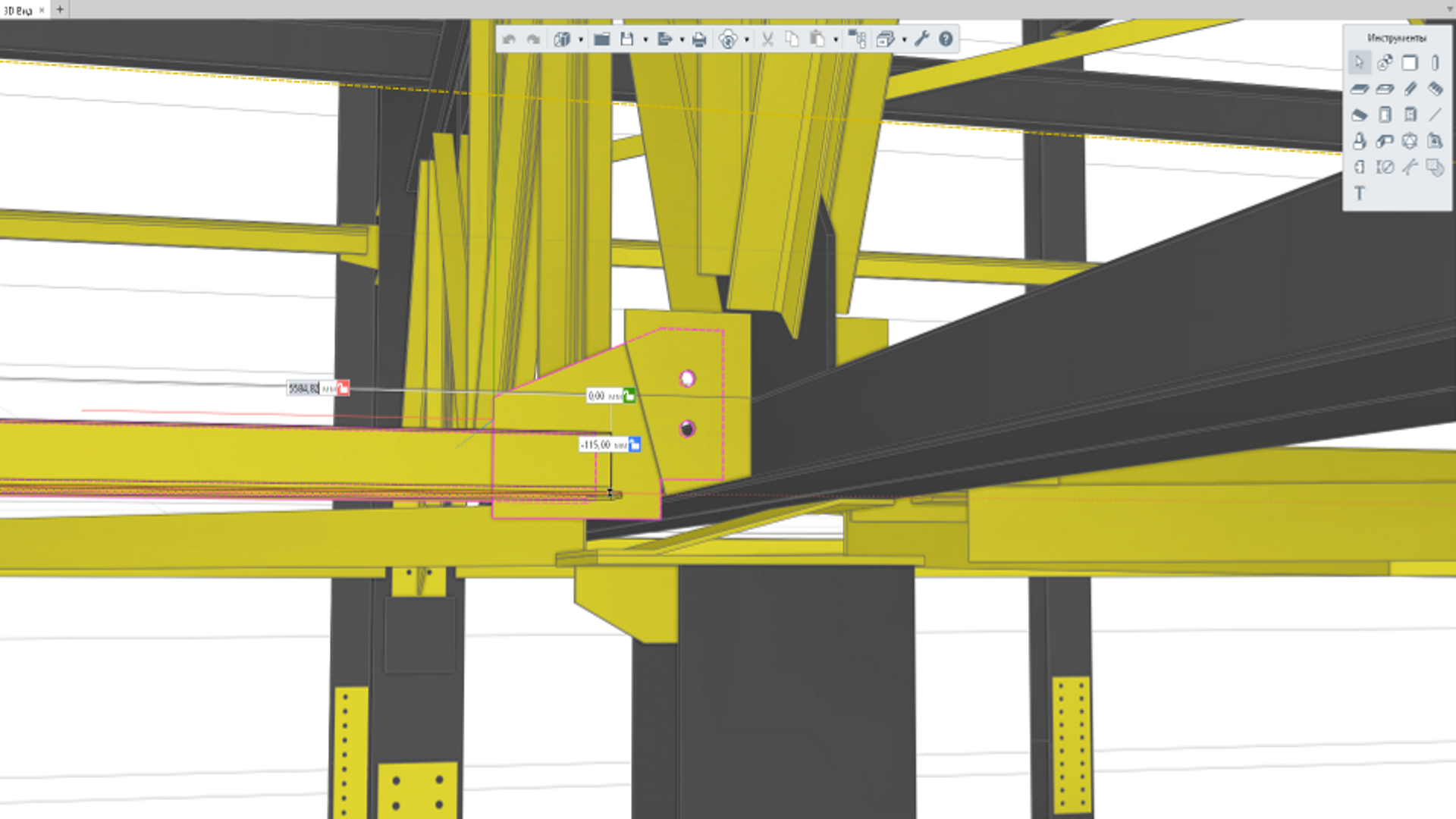
Figure 2: Steel Structures Design
Better Communication with Other Project Members
In the Renga BIM system, structural engineers, architects and MEP engineers work in a single environment with the same 3D model. Each member of the project team can track the changes their colleagues have made. This feature reduces the chance for discrepancies between architectural, structural and MEP models, validating the accuracy and consistency of the model. It also shortens the approval cycle.
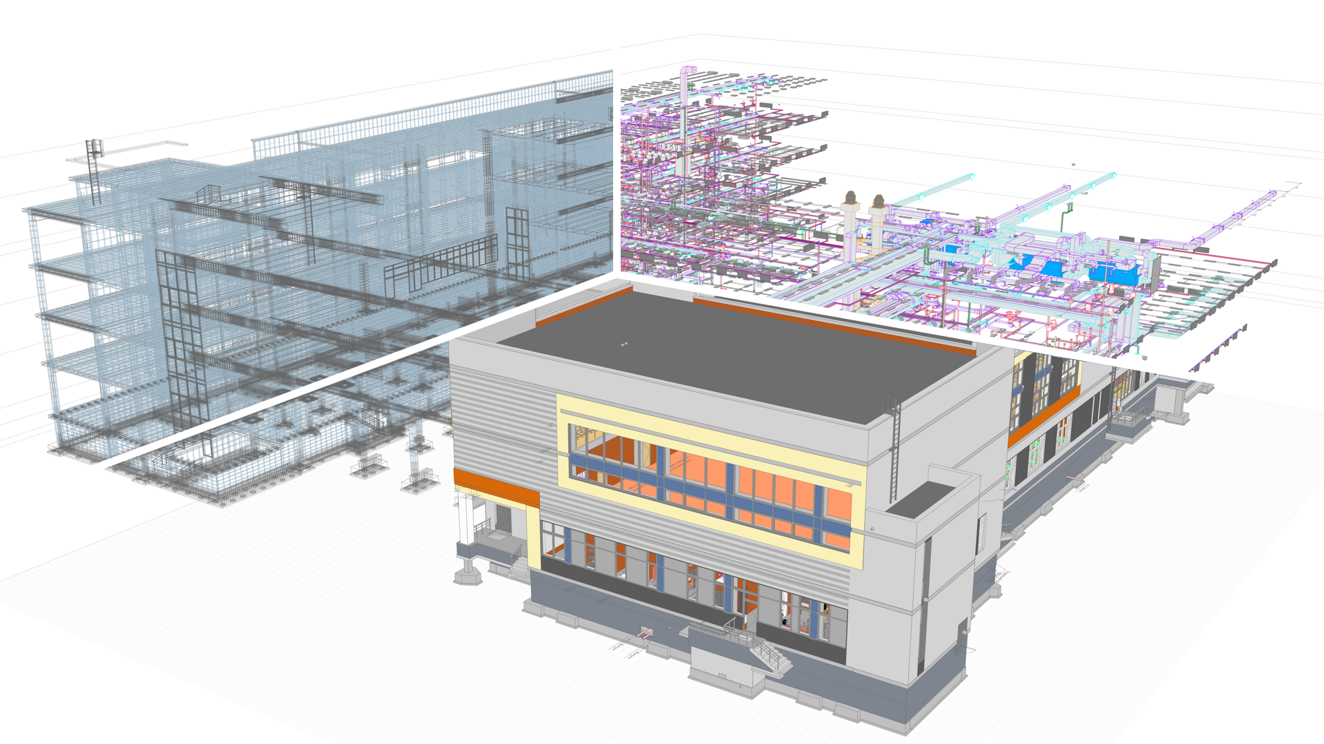
Figure 3: Better Communication with Other Project Members
Automated Scheduling
The software allows users to design an information model of structural building components and provides a rich tool to drive important workflow processes such as creating drawings of structural steel, reinforced concrete, architectural and structural drawings and many others.
Creating and maintaining accurate schedules can be complex, error-prone, and time-consuming. However, Renga automates this task by linking the schedule to the original Renga designs. When creating a structural 3D model, the engineer assigns the model with digital and user data (material, volume, quantity, name of structural elements, etc.). Based on this data, Renga automatically generates schedules that a user can insert in the drawing or share with other project team members.
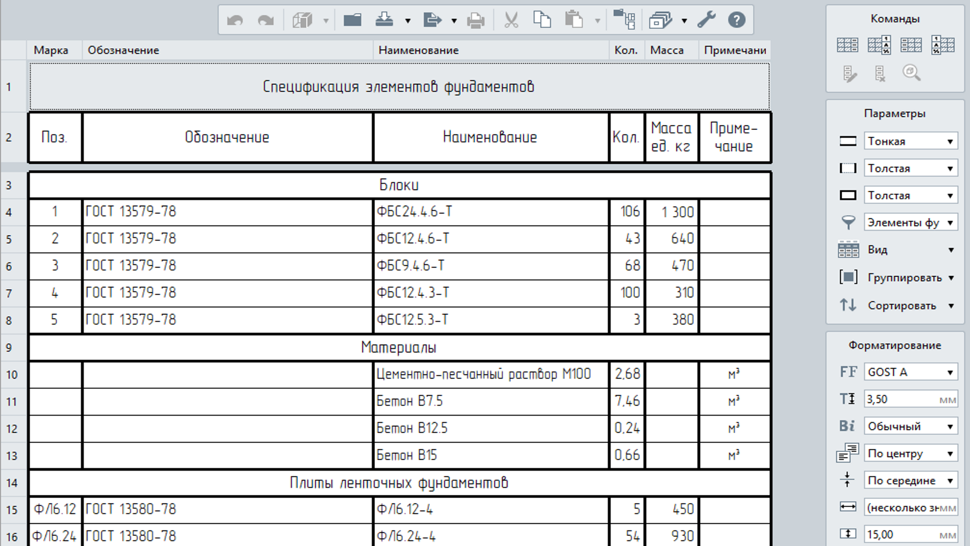
Figure 4: Automated Scheduling
Automatic Drawings Generation
Design an information model of structural building components and create drawings of structural steel, reinforced concrete, architectural and structural drawings and many others.
Drawing generation is automated in Renga, including structural elements layouts, trusses suitable for shipment, structural element connections, and many more. The structural engineers only need to add views of a building’s 3D model and generate the drawing using the Drawing Editor tools.
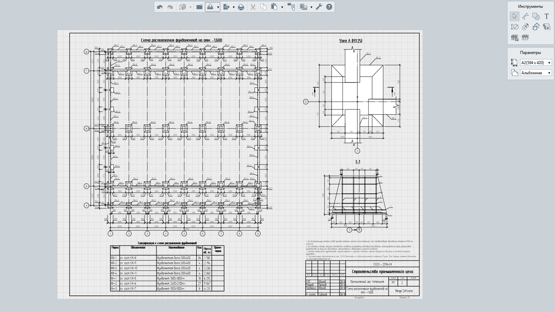
Figure 5: Automatic Drawings Generation
Quick Design Adjustments. 3D Model and Drawings Relationship
In the case of unexpected adjustments, Renga Software allows for quick and easy modifications to design documents. Information models are linked to drawings and schedules. Therefore, any modifications of the 3D models are reflected instantly in any construction documents, and all plans, layouts, joints, sections schedules, etc. will also change automatically. As can be seen from the above, Renga software is an efficient and very helpful tool with all essential functionality with a lot of benefits for structural engineers.
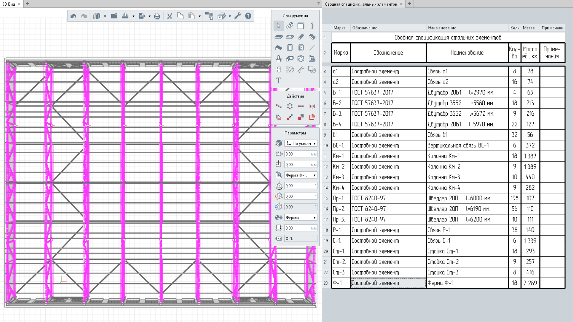
Figure 6: Quick Design Adjustments. 3D Model and Drawings Relationship
Preconstruction Project Visualization
BIM 3D modeling offers more visual way to improve spatial and architectural design, and make decisions quickly and efficiently. Structural engineers can visually detect clashes and eliminate them instantly.
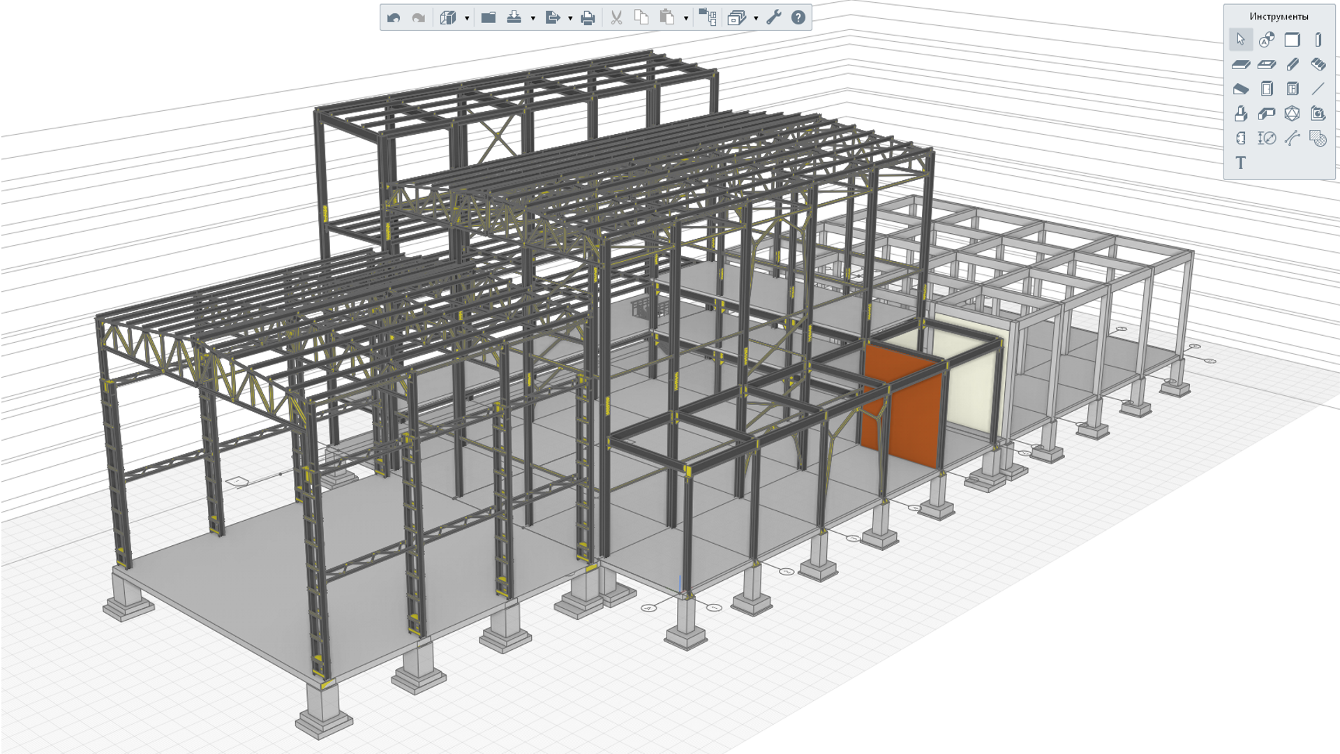
Figure 7: Preconstruction Project Visualization
3D Design Instead of 2D Drafting
Object-oriented design tools implemented in Renga allow users to have the geometric parameters and digital data from all model elements. Using Style Editor, a structural engineer can apply any type of modification to all objects. For example, if you need to use beams and columns with non-standard cross sections at the building structural scheme, you can use Profile Editor.
This tool creates profiles for columns and beams of any complexity and configuration. Automatic schedule and drawing generation from 3D models allow for project documentation to be generated within minutes.
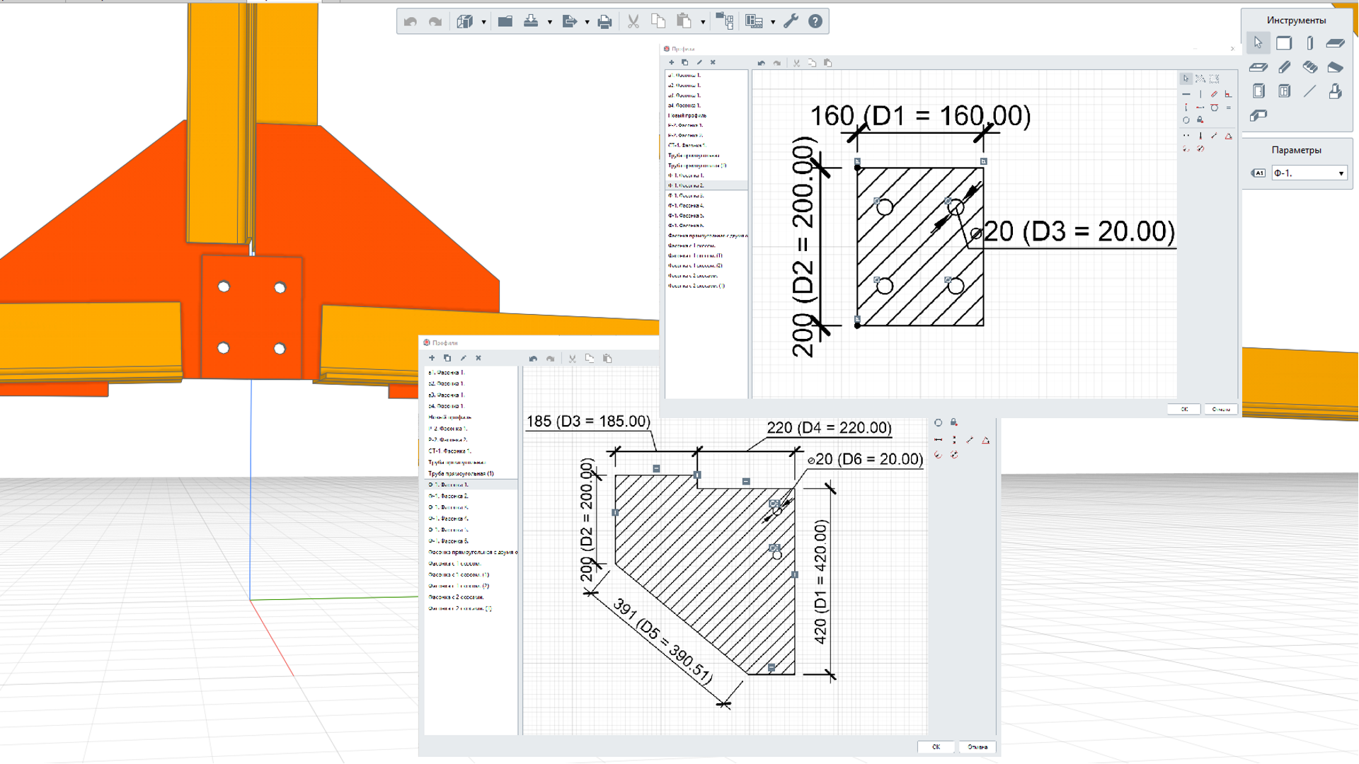
Figure 8: 3D Design Instead of 2D Drafting
Preparing Data for Analysis Software
When a 3D model has already been created in Renga, a structural engineer does not have to re-create it in analysis software all over again. All that is needed is to export the model to the IFC format and transfer it to any optional structural analysis software tool (for example LIRA-SAPR, SCAD Office, etc.). After a finite-element building model is created and joints and nodes are refined, a structural analysis software checks structural parts for load capacity and structural integrity.
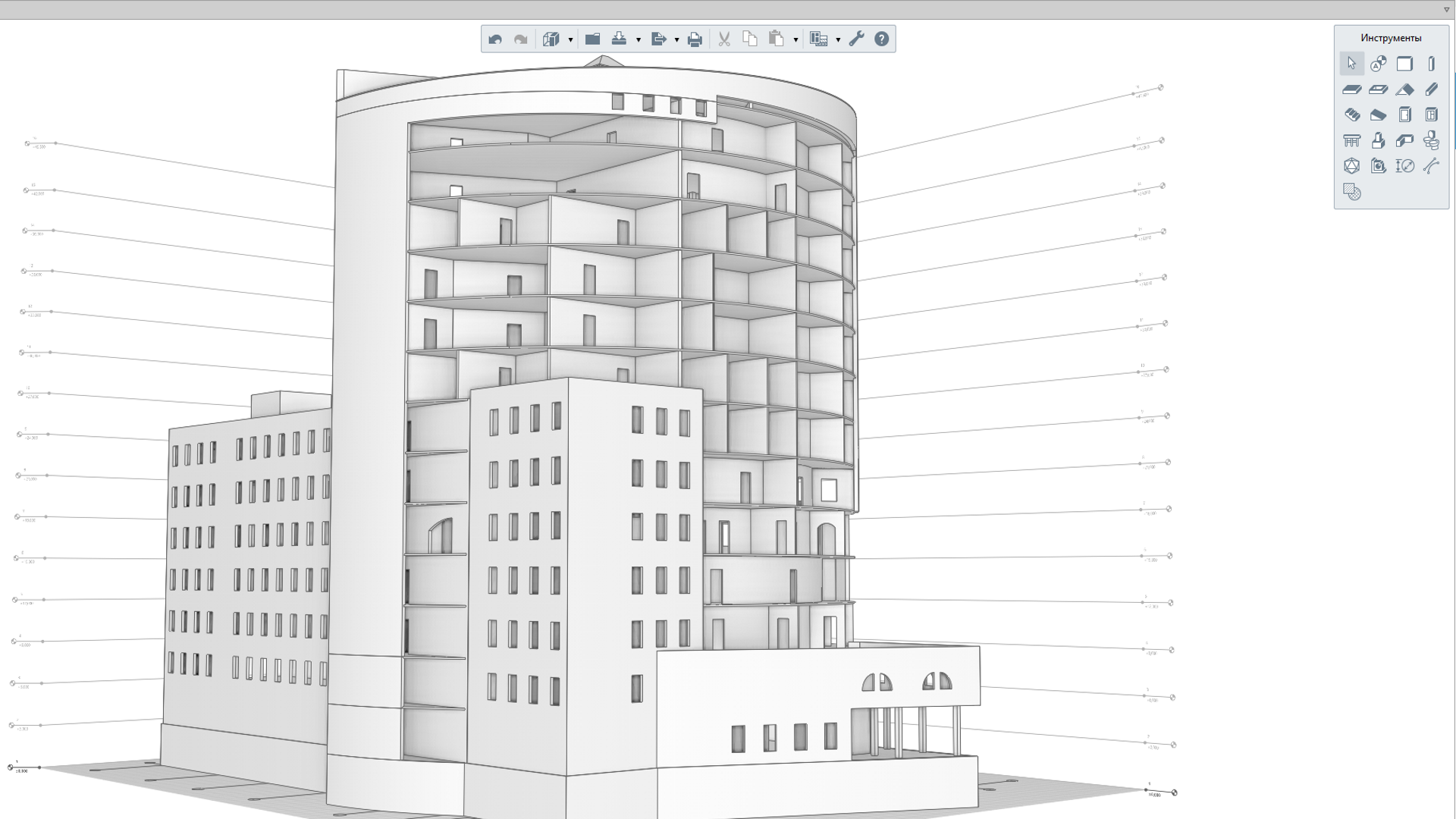
Figure 9: Preparing Data for Analysis Software`
Create Documents Compliant to Russian and International Standards
Renga automatically generates all documents according to the standards of Russian System of System of Design Documentation for Construction (SPDS) and International Organization for Standardization (ISO).
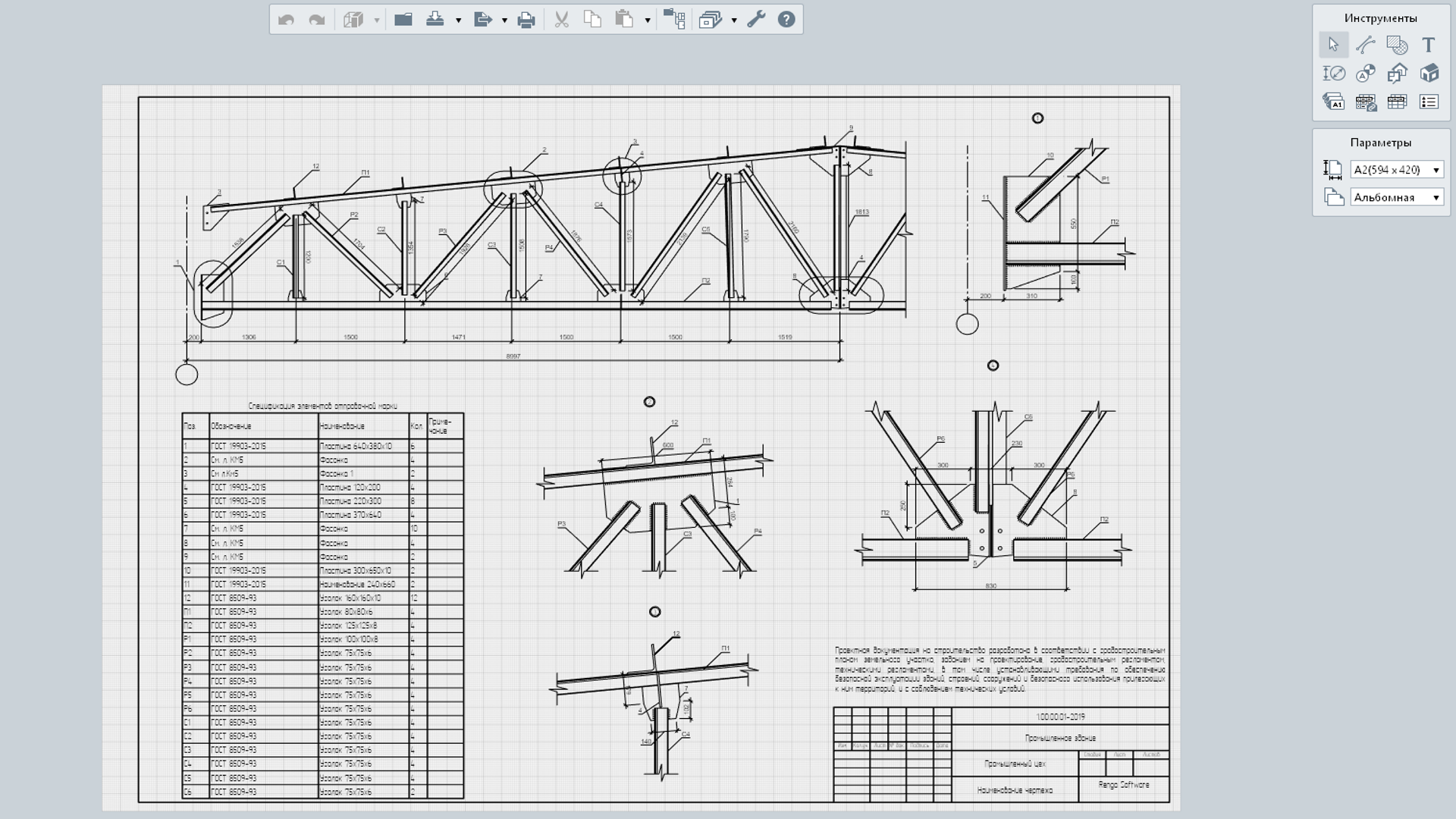
Figure 10: Create Documents Compliant to Russian and International Standards
Supported languages
english
russian
System Requirements
Мinimum System Requirements:
- Processor: 64-bit (x64) processor with 2GHz clock speed or higher
- Memory: 4GB for 64-bit system
- Video adapter: Graphics board supporting DirectX 10, Shader Model 4.0, true color mode
- Monitor: 1280x1024 minimum resolution
- Input device: Three-button mouse
- Operating system: Microsoft Windows 7 SP1 with Platform Update for Windows 7 64-bit version
Recommended System Requirements:
- Processor: 4-core Intel Core i5, i7 or similar AMD 64-bit processor with 3GHz clock speed or higher
- Memory: 16GB RAM or more
- Video adapter: NVidia GTX77x, such as GeForce GTX 970, GeForce GTX 980, GeForce GTX 780 AMD graphics board with DirectX 11, Shader Model 4.0, true color mode
- Monitor: 1920x1080 resolution
- Input device: Three-button mouse
- Operating system: Microsoft Windows 10 (64-bit)
Producer
Renga
FREE DOWNLOAD
Runs for 60 days from the date of installation. Available in English
add-on
Artisan rendering for Renga
Artisan Rendering runs closely with Renga Architecture so that users can create high quality, photorealistic images of buildings and structures they design in Renga Architecture.
Artisan Rendering was developed specifically for ASCON Group by PICTOREX Ltd, one of the leading international suppliers of visualization solutions.
add-on
Model Explorer
Extend your design development capabilities and explore more options for working with 3D model by using this effective tool. It provides quick access to parameters of selected element, allows to change custom properties value and control object visibility.