Online academy: Videos

We use cookies to help provide you with the best possible online experience

Design with ASCON Solutions:
Powerful Functionality • Easy-Learning • Cost-Effective

What's new in KOMPAS-3D v24

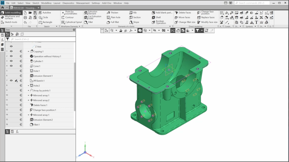
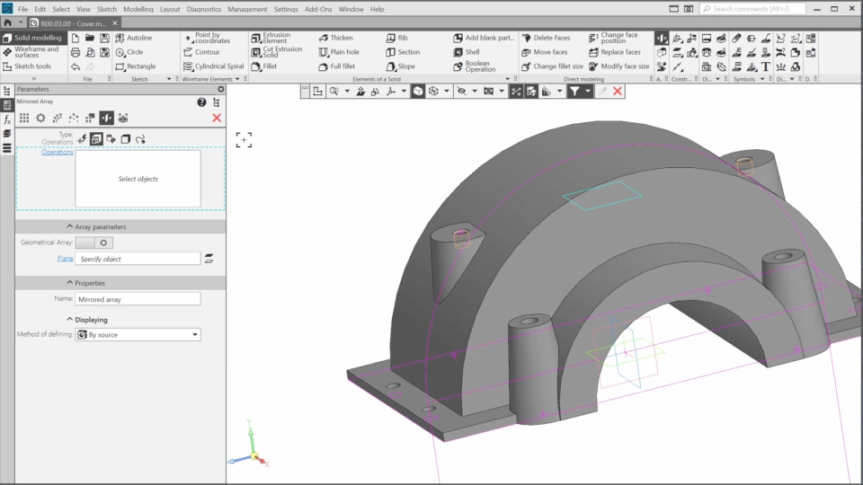
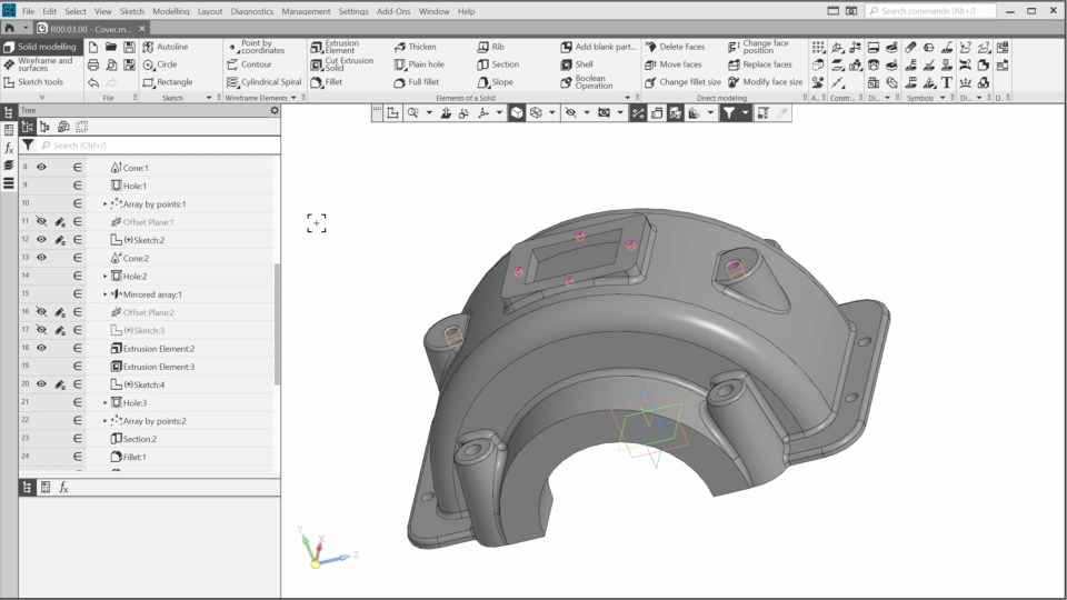
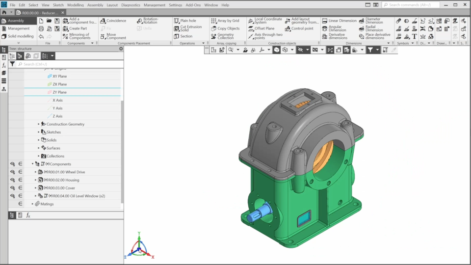
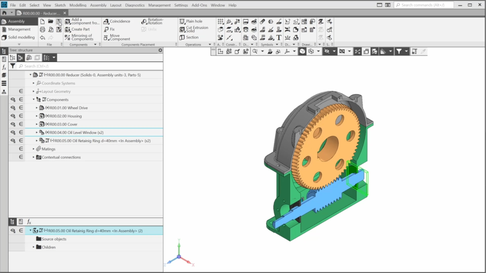
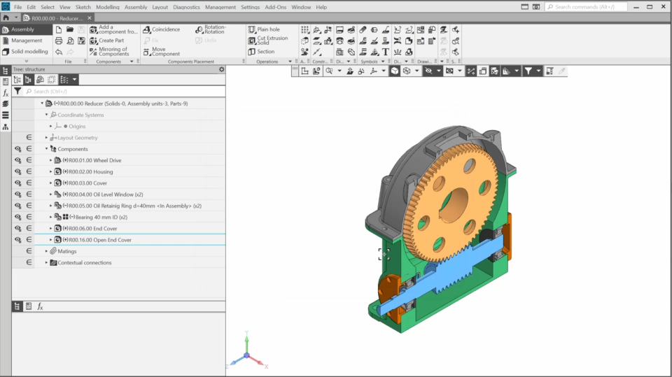
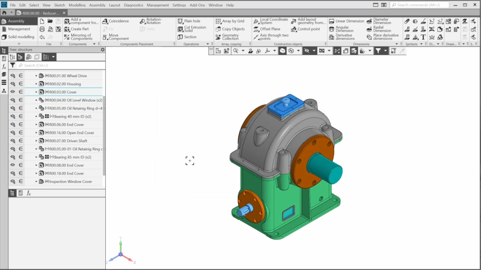
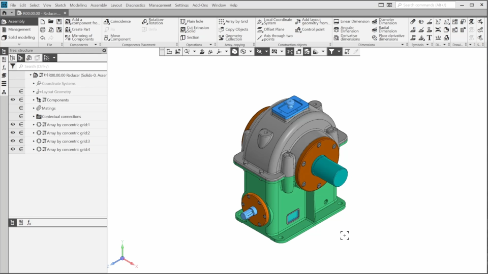
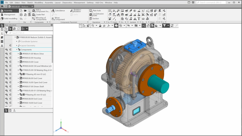
In the course, we’ll create the reducer from scratch. We’ll start with the layout geometry and then gradually create and add all the necessary components. Some components are ready-made. We’ll import some of the other components and use direct editing tools to modify them. The remaining reducer components will be created from scratch.

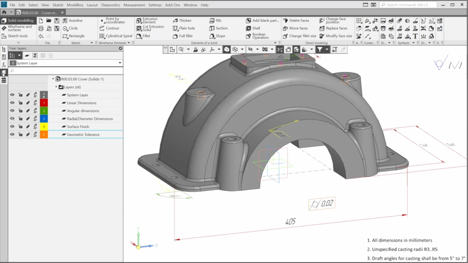
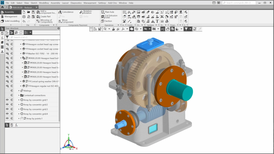
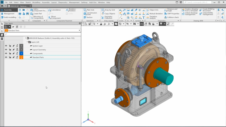
We’ll learn new functionality and also use standard Kompas features. We’ll explore layers in both part and assembly documents.Then, we’ll add standard parts using an application on the POLYNOM:MDM platform.

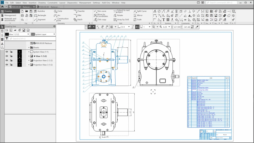
Finally, we’ll create the reducer drawing and the Bill of materials.

0.0 New functionality overview (9:19)
In this video, you will see what new features have been added to KOMPAS-3D v24 and how you can use them.
1.1. Creating the Worm Drive Layout Geometry (8:17)
In this lesson, we’ll start creating the layout geometry of the reducer.
1.2. Creating the Layout Geometry for the Reducer Components (9:58)
In this lesson, we'll continue creating the layout geometry for the reducer components.
2.1. Creating the Housing. Part 1 (8:13)
In this lesson, we’ll start to create the first reducer component. It will be the housing. We’ll export a blank model designed in another CAD system and check it. Then, we’ll add the bosses and the holes using new functionality.
2.2. Creating the Housing. Part 2 (5:58)
In this lesson, we’ll finish the housing that we started in the previous lesson. We’ll edit the housing elements using the direct modeling tools, add fillets and rounding surfaces. Finally, we’ll adjust the display of the smooth edges.
3.1. Creating the Cover. Part 1 (7:40)
In this lesson, we’ll start creating the cover from scratch based on the layout geometry. We’ll create the cover base using standard commands and add the conical bosses with holes to it.
3.2. Creating the Cover. Part 2 (8:52)
In this lesson, we’ll continue to refine the cover. We’ll add two conical bosses and a rectangular hole to the cover. Finally, we’ll round all the sharp edges and finish the cover geometry.
3.3. Creating the Cover. Part 3 (11:36)
In this lesson, we’ll add details to the model, such as general notes and the majority surface finish symbol. We’ll also create dimensions, surface finish and tolerance symbols, and work with layers.
4.1. Adding the Components (9:10)
In this lesson, we’ll start the reducer assembly. We’ll add the worm drive, housing, and cover. We’ll create a new subassembly directly in the reducer assembly, add local parts and edit them.
4.2. Versions and Variants (6:53)
In this lesson, we’ll find out how to create variants of the geometric representation of the model to analyze the model in various operating states. Also, we’ll create a new version of the part.
4.3. Adding Bearings and End Covers (6:47)
In this lesson, we’ll add the bearings to the worm. We’ll place the end cover on one side of the worm. Then, we’ll use the same model as a blank to create the open end cover and place it on the other side.
4.4. Adding the Wheel Components (11:13)
In this lesson, we’ll continue adding components to the reducer. We’ll add the driven shaft, the oil retaining rings, the bearings and the covers. We’ll modify the components to match each other using both the solid modeling and direct editing tools.
4.5. Adding Standard Parts. Part 1 (7:07)
In this lesson we’ll learn how to add standard parts to the assembly using “Standard Parts for KOMPAS” – an application on the POLYNOM:MDM platform, included in the KOMPAS-3D distribution.
4.6. Adding Standard Parts. Part 2 (6:24)
In this lesson, we'll continue adding standard parts. We’ll create bolted connections in the conical boss holes. We'll edit the standard bolt using the direct modeling commands.
4.7. Adding Standard Parts. Part 3 (4:41)
In this lesson, we’ll finish adding the standard parts. We’ll insert screws and washers for the inspection window cover, add two eyebolts to the cover, and place the key into the shaft keyseat.
4.8. Layers in the Assembly (2:41)
In this lesson, we’ll learn how to manage layers and their properties in an assembly document.
5. Creating the Drawing and the BOM (7:36)
In this lesson, we’ll learn how to work with the product structure using the “Product BOM” panel. We’ll generate the reducer drawing, the bill of materials and balloons.

The content on this page is available to authorized users only. Please sign in.