Creating an assembly in KOMPAS-3D CAD Modeling Software with a Free Trial

We use cookies to help provide you with the best possible online experience

Design with ASCON Solutions:
Powerful Functionality • Easy-Learning • Cost-Effective

The Self-Centering Vice

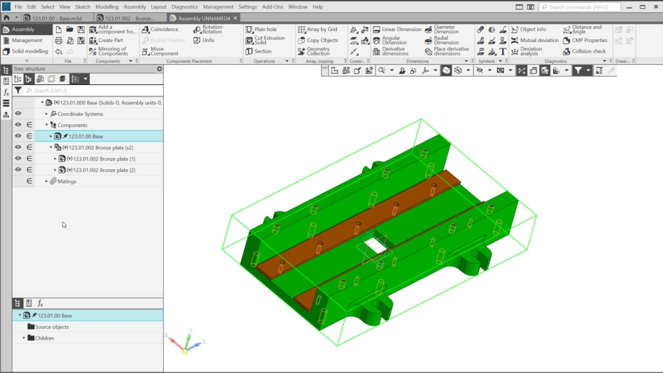
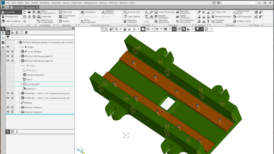
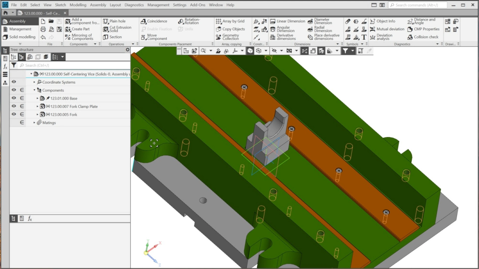
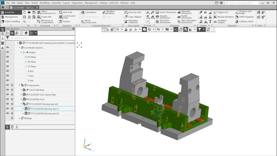
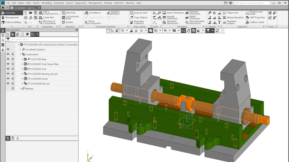
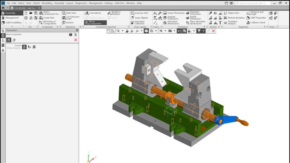
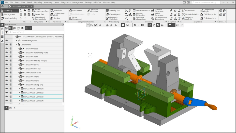
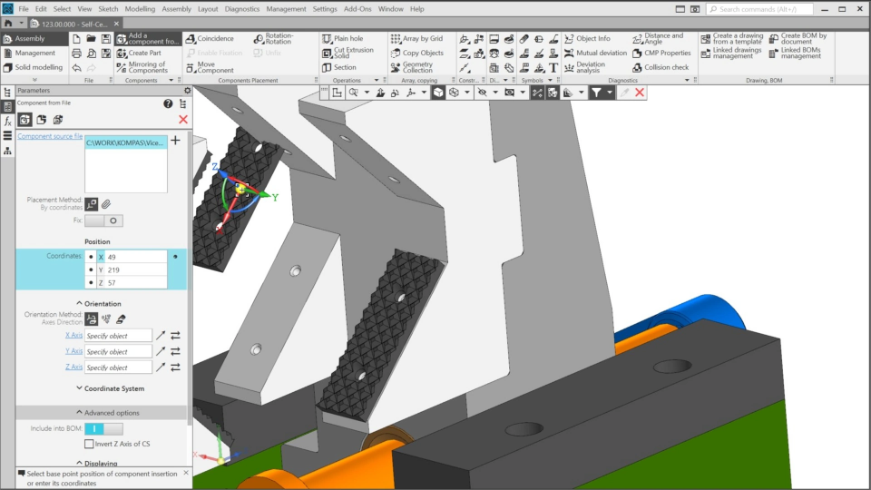
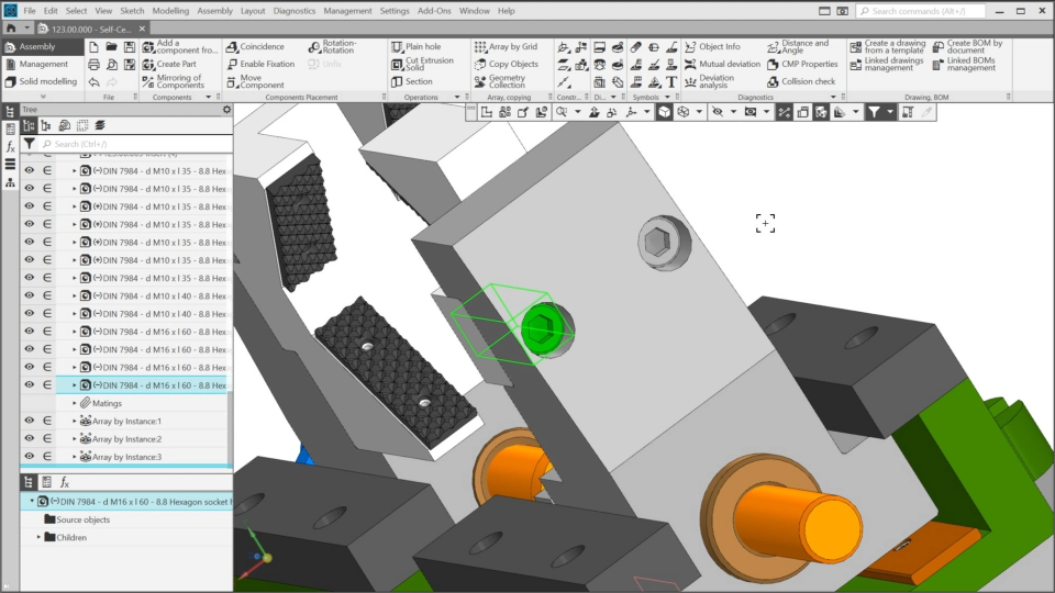
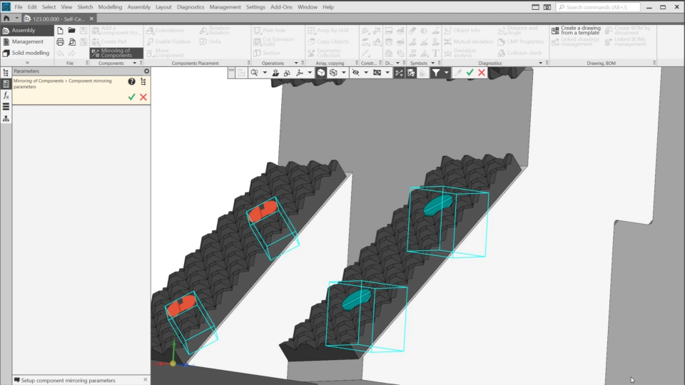
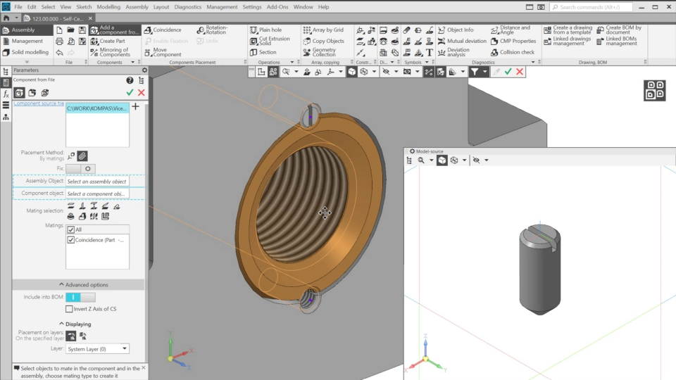
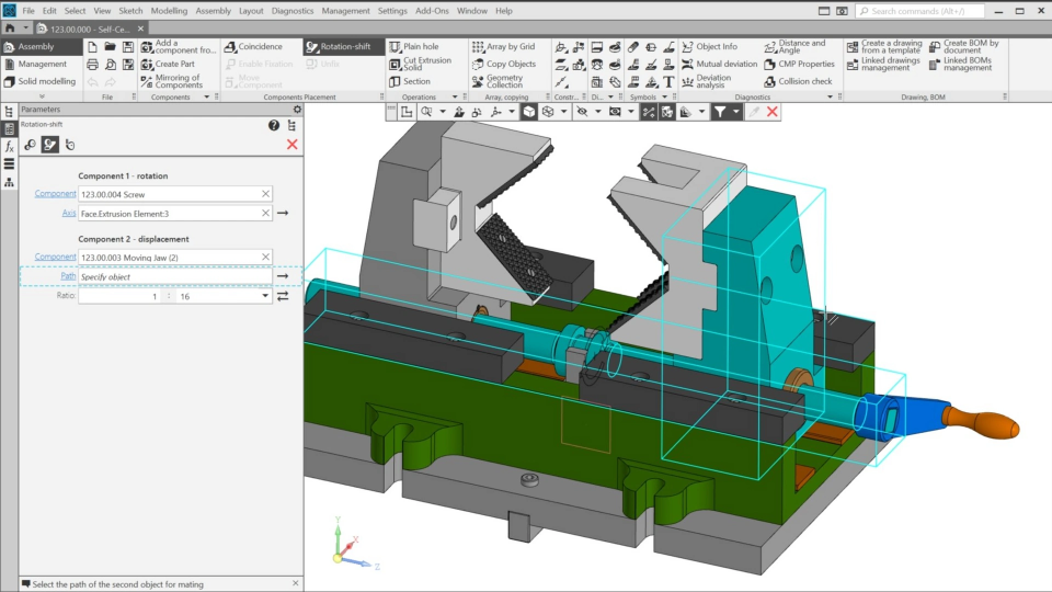
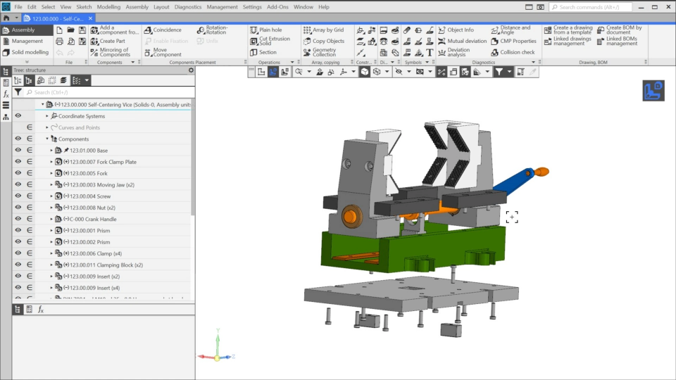
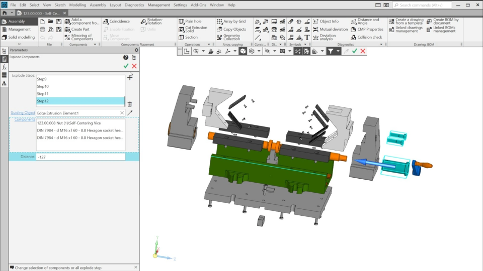
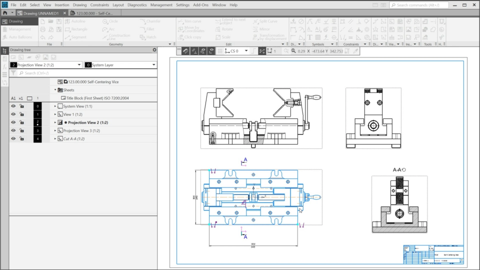
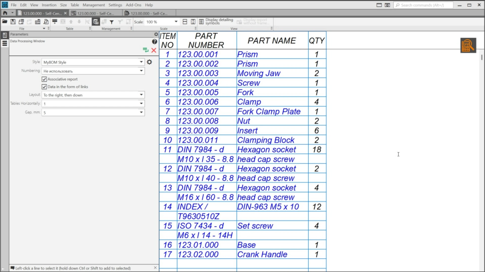
In this course, we’ll create an assembly – the self-centering vice. It will consist of more than sixty components, including two subassemblies. We’ll define component positions using different matings. Also, we’ll add a mechanical mating that will allow us to simulate the vice’s operation.Then, we’ll create an exploded view and learn how to edit it. We’ll generate a drawing, add a bill of materials, and create balloons.

01. Creating the Base Subassembly (7:12)
In the first lesson, we’ll start creating the first subassembly, which consists of three parts: the base and two bronze plates.
02. Adding Standard Parts to the Base (3:08)
In this lesson, we’ll add fasteners to the Base.
03. Getting Started with the Vice Assembly (3:46)
In this lesson, we’ll create a new assembly and begin to add the components into it.
04. Adding the Moving Jaws (4:34)
In this lesson, we’ll continue adding components to the Vice assembly.
05. Adding the Screw and the Nuts (3:43)
In this lesson, we’ll continue adding components to the vice assembly and insert the screw and the nuts.
06. Adding the Crank Handle and the Prisms (4:54)
In this lesson, we’ll add the crank handle subassembly, which was prepared in advance, and two prisms.
07. Inserting the Clamps (4:58)
In this lesson, we’ll add four clamps to the assembly, and two of which will be added by mirroring.
08. Adding the Clamping Blocks and the Inserts (6:26)
In this lesson, we’ll add two clamping blocks to the vice and six inserts.
09. Adding the Hex Screws (7:52)
In this lesson, we’ll start adding fasteners to the self-centering vice assembly.
10. Adding the Countersunk Screws (3:06)
In this lesson, we’ll continue to insert the screws into the assembly.
11. Adding the Slotted Set Screws (7:31)
In this lesson, we’ll create holes in the assembly and insert the screws into them. We’ll use the isolation mode to hide objects that we don’t need at the moment and create auxiliary objects to help us to place the holes.
12. Adding a Mechanical Mating (4:15)
In this lesson, we’ll simulate the vice operation using a mechanical mating.
13. Creating Exploded Views (6:49)
In this lesson, we’ll learn how to create and adjust exploded views.
14. Editing Exploded Views (2:51)
In this lesson, we’ll learn how to edit exploded views. We’ll move the components that haven’t been exploded yet.
15. Preparing for the Vice Drawing (3:47)
In this video, we’ll prepare the assembly for drawing generation. We’ll adjust the front view and create a controlled variable for the handle position.
16. Creating the Vice Drawing (8:04)
In this lesson, we’ll generate three views of the assembly and add several broken-out sections.
17. Adding a BOM to the Drawing (5:46)
In this lesson, we’ll add a BOM to the drawing and generate balloons.

The content on this page is available to authorized users only. Please sign in.