This is a post created by Stanislav Stepanov, CEO, MK Rez. He shares his experience of cutting tools design in KOMPAS-3D.
We design indexable tools and replaceable carbide inserts. From the very beginning of our operations, we recognized the importance of having a reliable software partner capable of providing stable solutions and long-term technical support. We quickly realized that ASCON was the most mature CAD vendor, and choosing KOMPAS-3D was a logical decision.
In 9 years, we have completed a large number of projects for various industries ranging from heavy equipment to aerospace, automotive, and oil&gas sectors. We have evolved from simple to more complex designs.
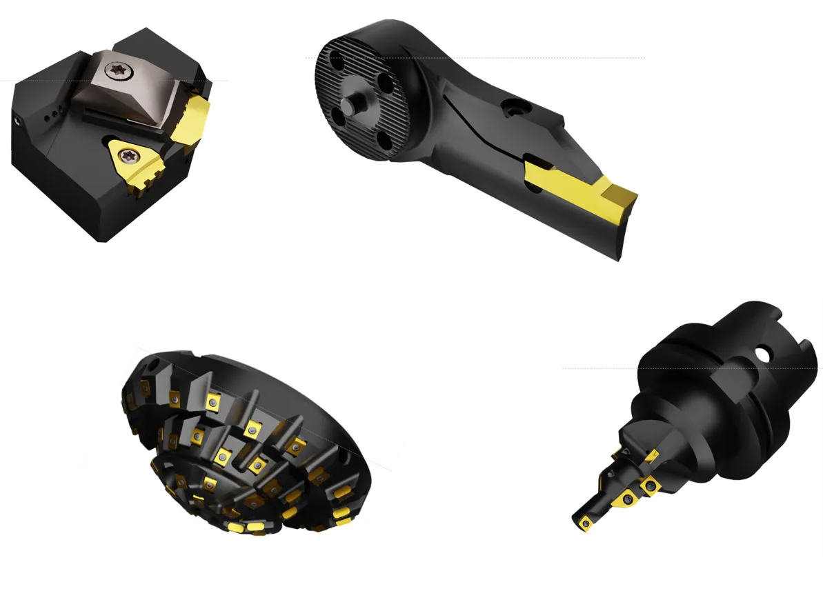
Every customized tool project presents a significant challenge and involves a great deal of design and manufacturing planning. Many tools require special attention to their structural rigidity. We have gained extensive expertise in analyzing blade geometry, studying hydraulics for tools designed for high-pressure coolant delivery systems operating at pressures of up to 300 bar, developing chip-breaking geometries, and creating curved milling inserts with complex cutting edges.
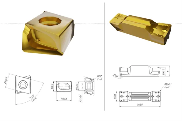
We begin with the components we design:
- Cutting insert
- Insert pocket
- Toolholder.
Let us consider how inserts are placed into the toolholder.
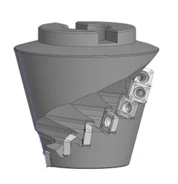
One of the most complex types of tools is the corn cob indexable milling cutter. Such milling cutters often have at least three different types of pockets for the same type of inserts. The design requirements are:
- Accessibility of the pockets for machining (product manufacturability)
- Insert positioning at the correct cutting angles
- Compatibility with the machine tool is also a design-for-manufacturability issue.
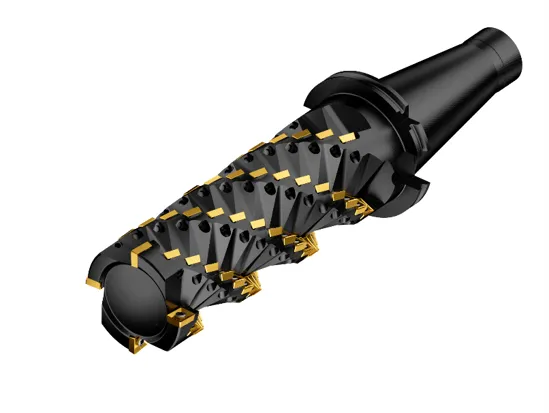
To model each pocket, we create a new body to be used in a Boolean operation. At first glance, such an approach may seem unnecessarily complicated, involving a large number of geometric features. However, it is used to simplify inspection of the pocket geometry and ensure that the pocket can be manufactured efficiently.
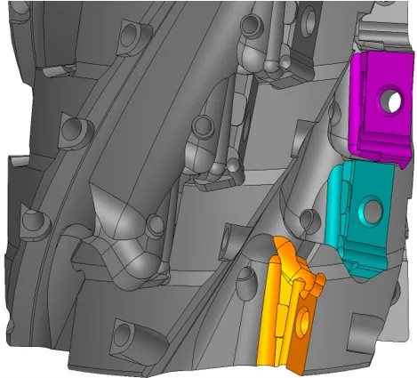
Each surface of the pocket is created using a modeling operation that represents the machining operation. Each body subtracted by a Boolean operation represents the toolpath. A body can represent a drill bit, milling cutter, or countersink.
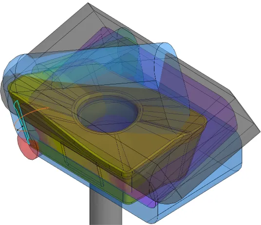
For such an approach, we use the KOMPAS-3D operation called sweeping. With sweeping, we can create fairly realistic flutes on milling cutters and drill bits. Using any other path-based cutting operation may result in distortions and degenerate geometry. A swept cut, created by moving a body along a path, ensures that the feature can be machined, supporting design for manufacturing.
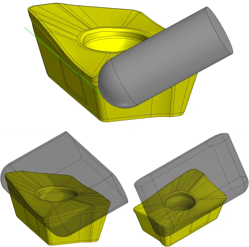
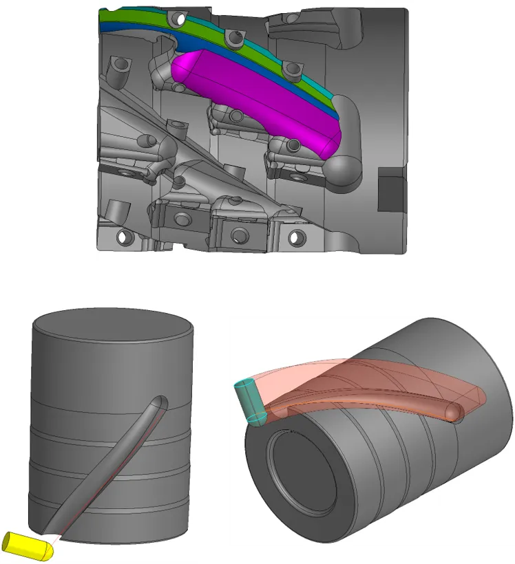
Once all the auxiliary bodies are constructed and the Boolean operation is performed. We see that:
- The pocket is fully "machined"
- We are reasonably confident that all surfaces are accessible, and the pocket can be machined.
This approach has greatly reduced design errors. Using a single auxiliary body to cut a pocket is prone to errors, as it is very easy to skip or misalign one of the surfaces. This leads to manufacturing defects 99% of the time. Using multiple auxiliary bodies in a Boolean operation eliminates the very possibility of such errors.
The next step is to position the insert to achieve the required cutting angles. We snap reference points on the insert to the auxiliary surfaces machined by the designed tool.
Then, we verify the geometric accuracy of the surface generated by the insert's cutting edge. Providing the required cutting angles is not enough; we must also ensure that the insert generates the required workpiece geometry, such as a vertical wall or a specified profile.
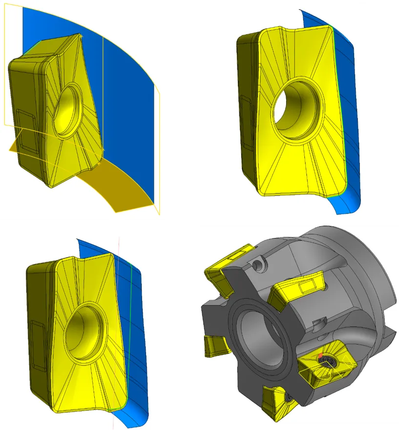
Another extremely useful tool in KOMPAS-3D is collision detection. When we position two solids relative to each other, we check for any unintended intersections or interference between their surfaces.
Boolean operations are one of the most useful tools for our routine work. For example, we apply it to create multiple standard milling and drilling toolholders. With a library of auxiliary bodies for Boolean operations available, a new tool design can be developed very quickly.
Patterns are another extremely important tool for us. A great example is how we use patterns to design corn cob milling cutters.
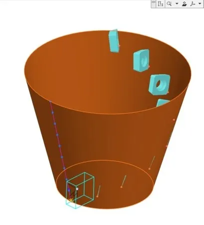
Most often, we use point-driven patterns. The underlying points can be positioned as required. In addition, multiple model configurations are created by enabling or disabling Boolean operations for individual pattern instances. As a result, with a library of auxiliary bodies for Boolean operations and point-driven patterns, modeling a corn cob milling cutter becomes fairly simple. However, this is true only if the designer knows how to use these operations effectively. The importance of the designer's skills should not be underestimated.
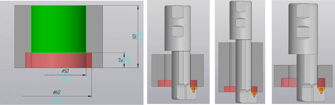
As to process automation, we are doing our best. For example, we are creating various libraries and using model parameterization. KOMPAS-3D is a great solution to automate standard design tasks. Some cutting tools can be represented as parametric models. An example is a cutter to machine back spotfacing tools. The designer specifies the spotfacer diameter, overhang, and shank dimensions to generate a model and drawing for customer approval.
KOMPAS-3D is an open platform with an API for third-party integrations. Our next step in automation is to create a user interface that allows users to define product parameters and automatically generate design deliverables in KOMPAS-3D.
Afterword: "Our experience in tool design has driven us to focus on automation and standardization, although 90% of our products are custom-designed and unique. With KOMPAS-3D, we have reduced design time from several days to a couple of hours, eliminated errors, and improved manufacturability."